


If you do not know how to solder, it is recommended you practice first with something like https://www.sparkfun.com/products/14635 or a spare board before this.
Soldering is used to make an electrical connection between two parts. It involves melting the solder with the soldering iron (at 250° - 350°C) and touching the molten solder onto where the connection is needed. There are many excellent soldering tutorials on youtube like the one below.
Hint: To keep the female t connector from deforming, it is a good idea to plug the male one in to keep the shape while soldering.
Solder the black wire to the horizontal pin and red wire to the vertica pin of the T connector.

The result should look like this:


It is important to solder the header pins straight, and not have them slanted
To break header pins into the right length, use your fingernails or a wire cutter on the indent between the pins where you want to make a cut.
With fingernail: Apply pressure as close you can to the fingernail to bend the header pin to minimise the chance of the header pin breaking at some other point.
With wire cutter: align the mouth of the wire cutter with the indent where you want to cut the header pin and squeeze.
Please cut the following length header pins:

Take a 14 pin header pin and put it in one side of the teensy, making sure all 14 pins go into a hole

Solder ONLY ONE pin first.
Inspect the header pin to see if it is slanted or has a gap. To fix any issues, (like a slanted header pin in the picture), melt the soldered pin and adjust the header pin, then remove the soldering iron to let the solder harden again.

Once the header pin looks like this, solder the rest of the pins.

Repeat the process on the other side with 14 more pins

Take the 3 pin header and put it into the inside 3 pins of the teensy. Solder 1 pin and make sure the header pin is straight without any gaps. Correct as needed like above, and solder the rest of the pins once done.

The result should look like this:


If you inserted the Male T connector into the female T connector when soldering the battery case, take the Male T connector out to use it in this step.
Insert the male T connector into the T shaped hole in the Zircon PCB.
Solder it in place. This will take more solder than usual because the pads are big.
Put the switch in the 3 holes. The direction does not matter. Solder all three holes and cut the excess length of pin with a wire cutter

Cutting female header pins is slightly different to cutting male ones. You will need to sacrifice 1 pin for each cut.
To cut female header pins, place a wire cutter exactly in the middle of the pin and cut. This will destroy the pin the wire cutter cut, but will result in no harm to the pins on either side.
Please cut the following length female header pins:

Place the 24 pin, 3 pin, and 1 pin long header pins in their respective holes (direction does not matter) and solder them.

Solder the 4 pin JST port into place. The direction DOES matter so make sure it is exactly like the image.

Insert the Infrared (ball) sensors in the 8 slots equally spaced around the perimeter of the main board and solder them. It helps to bend the pins after inserting, then solder, then clip the extra length of the pins

The result should look like this:


First, open the gear motor set.
Put the two black motor casing parts around the motor until it is snug. You may have to rotate the motor around so that the rectangular indent lines up with the black casing.
Use a screwdriver to secure the casing to the motor with two screws
Be especially careful with this step Use pliers to put the metal pin into the hole in the shaft of the motor.

This step requires some force, but make sure not to bend or break the pin. The shaft should look like this:

Solder a wire to each of the motor tabs. Make sure to not be too slow at soldering and melt the plastic of the motor.
Repeat for the other 2 motors.
The result should look like this:


Open an Onewheel set.
Take a green silicone bead and push two golden on each end
Repeat for a total of 18 beads.
Take a metal ring and slide 9 beads into it.
Do it again for the second ring

Take the four black center molds labled A, B, C, D and sandwitch each 9 bead ring between each pair

Take 3 bolts and 3 nuts (the smaller ones called m2) and secure the two wheels together.

Slide the omniwheel onto the shaft of a motor from Part 4.
Make sure the pin of the motor slides into the slot on the omniwheel.
If you have trouble here, it is probably because you mixed up the order of the black center pieces or put the omni wheel onto the shaft backwards.
Secure the omniwheel onto the motor by screwing an aluminum standoff onto the motor shaft.

The result should look like this:
repeat 3 times for each other motor

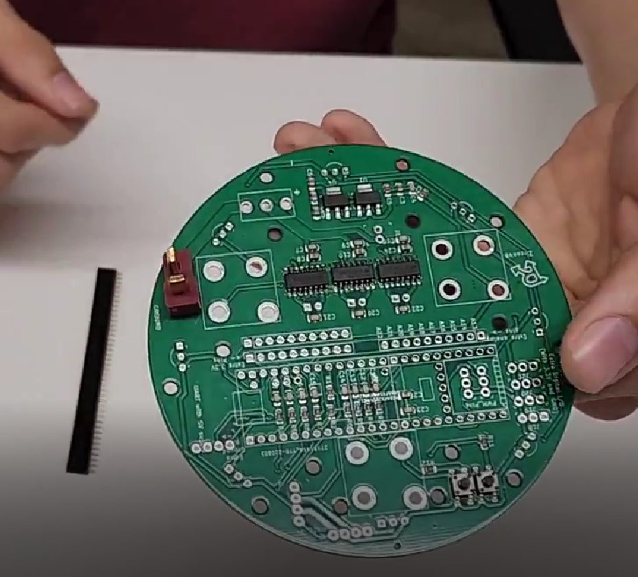
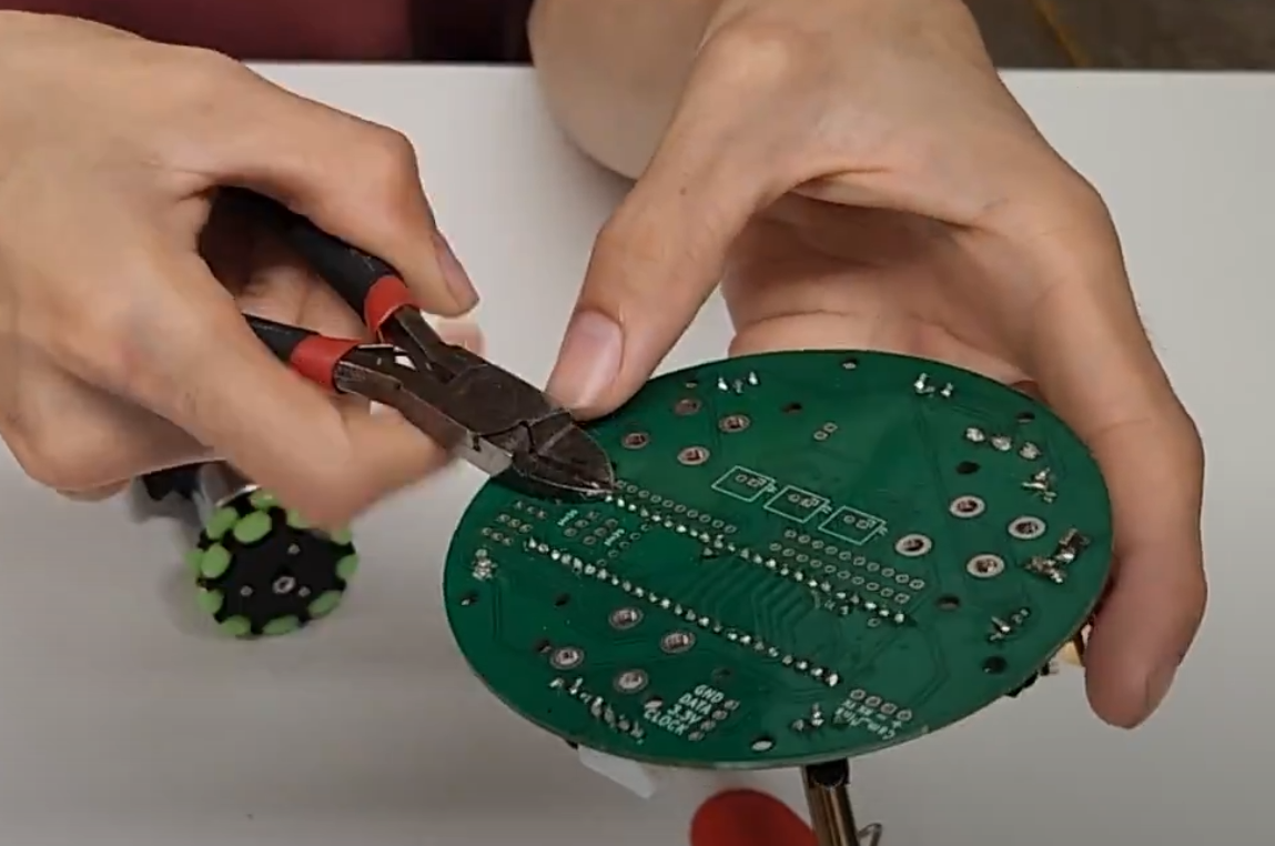
To mount the motors, we need as flat of a board as possible underneath where the motors will sit.
Use a wire cutter to cut any pins sticking out from under the Zircon board. Be careful not to damage the silkscreen (the green or black part of the Zircon board).
We will repeat the next steps 3 times for each motor. For this step, be sure not to overtighten the bolts and dig into the PCB. Tighten them comfortably but not too much. Get 4 m3 bolts (the larger ones) and m3 nuts. Secure the motor onto the Zircon board with the 4 bolts through the holes in the black casing.

Solder the motor wires into their respective pins Accidentally swapping the pins of the same motor is fine. The result would be the motor will spin in the opposite way than it is commanded (keep that in mind when programming).
Accidentally swapping pins from different motors is not fine, so if that happens please unsolder carefully and correct it.
Repeat these steps for the other 2 motors.
The result should look like this:


The line sensor board has 4 holes, of which 1 is placed closer to the edge. There should be 3 of the same shape on the Zircon board.
Use 4 bolts and 4 standoffs to sandwich the line sensor. The bolts should be screwed in from the side with electrical components (side DOES matter)
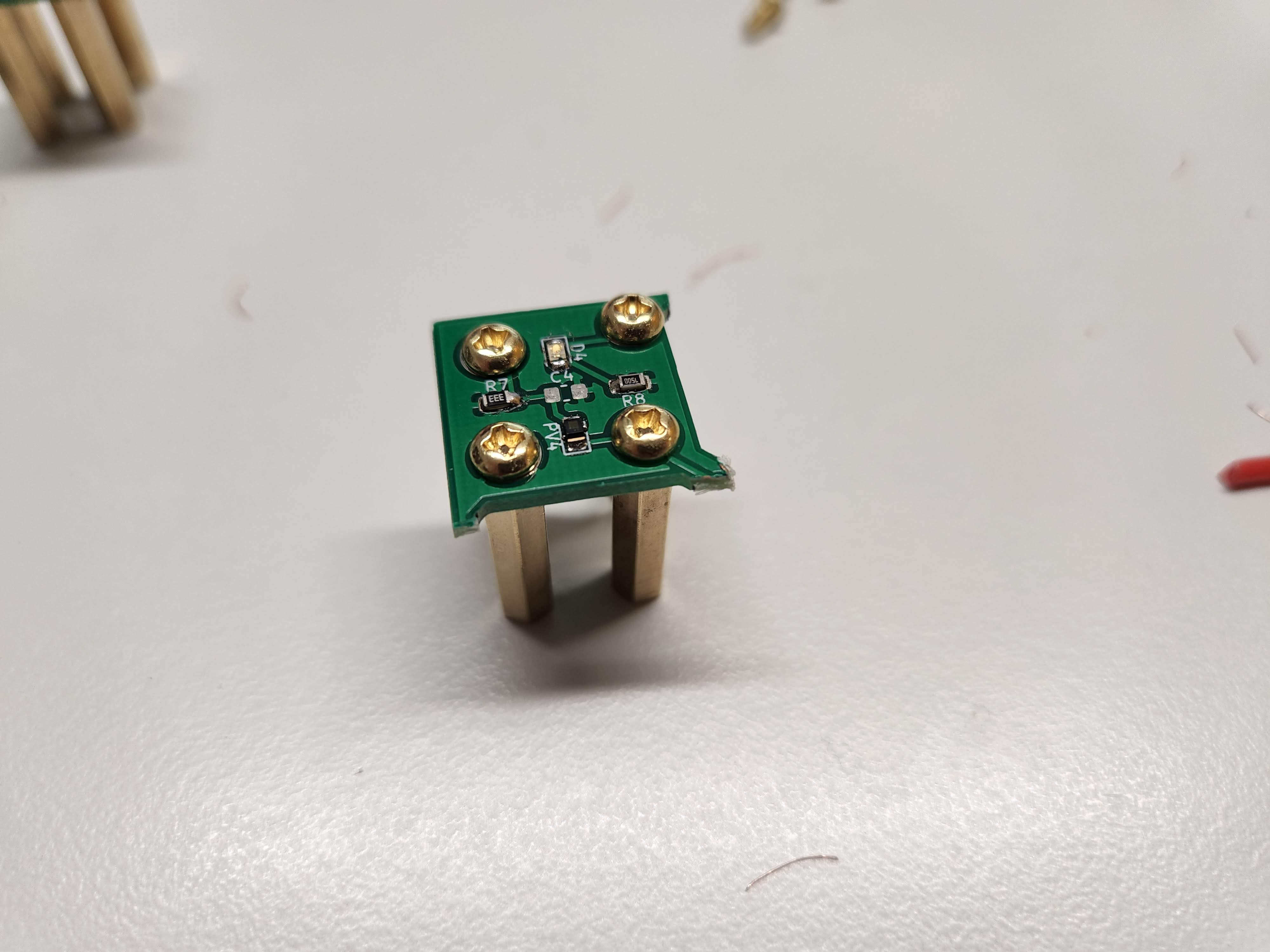
Attach the sensor to the Zircon board with 4 more bolts. The standoffs should be straight. If not, please make sure you put the line sensor in the correct orientation and facing down.
Repeat 2 more times.

The result should look like this:


Be careful with this step. Make sure not to bend any pins and make sure all pins are going into the slots they are supposed to.
Plug the teensy into the female header pins on the Zircon furthest to the right.
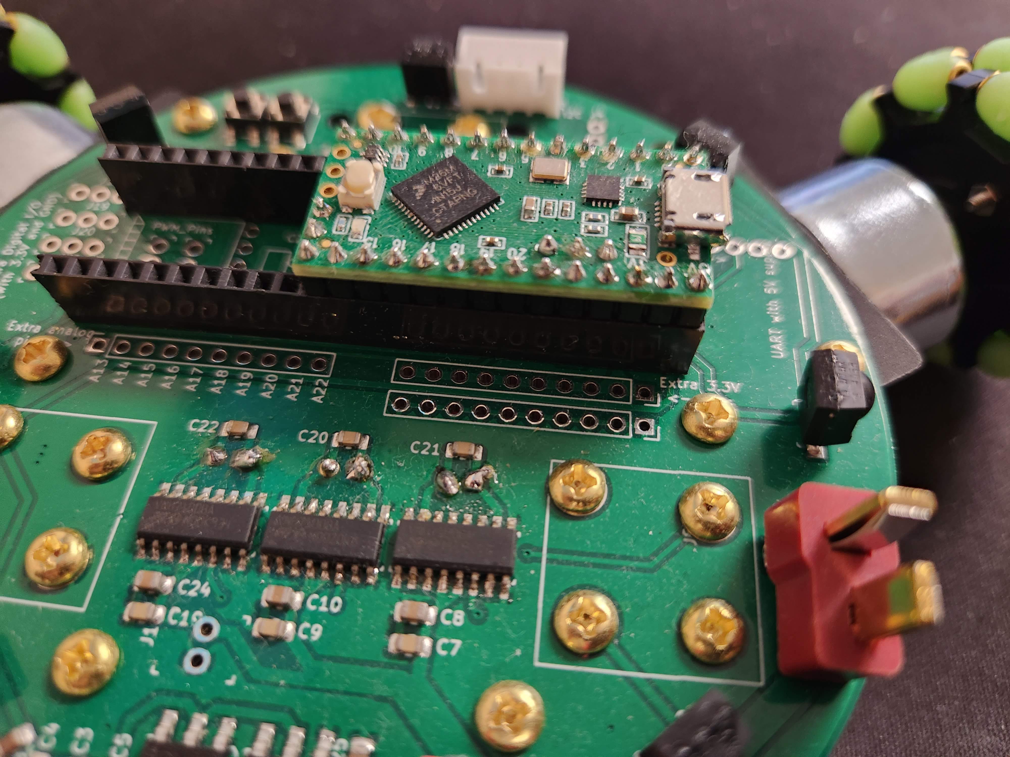
The reason there are extra female header pins on the Zircon that are unused is because the Zircon is compatible with the teensy 3.5 and 3.6 as well, which are longer than the LC that is included in the kit.
Inserting the teensy into the wrong slot or pins not going where they are supposed to can damage the kit, so please double check if the teensy is inserted in the correct spot and all pins are inserted (including the inner 3).

Insert the AA batteries into the battery holder. Set your voltmeter to measure voltage (around 6 volts if there is a setting on your voltmeter) Make sure the black probe of the voltmeter is on the COM port of the voltmeter and the red probe is on VΩmA.
Place the black probe into the vertical and black part of the T connector of the battery case. Place the red probe into the horizontal and red part of the T connector of the battery case.
The voltmeter should read POSITIVE 6 volts. If it reads negative, please unsolder and swap the red and black wires of the battery case. As a doublecheck, swapping the voltmeter probes should show NEGATIVE 6 volts. As an additional reference, here is a lipo battery with a T connector. The colors of the battery wires (red and black) connected to the T connector should be exactly like your battery case.

Now that you checked the battery is made correctly, plug it into the Zircon through the T connector. If the line sensors and teensy have not turned on (shown by an led),flip the big switch.
Take the compass sensor and connect it to the Zircon through its 4 pin cable. The compass should light up with a green LED. If the LEDs do not light up, unplug the battery and check if it is hot. Make sure you plugged in everything in the correct slot, line sensors are in the exact orientation they should be, and the 4 pin JST port is in the correct direction.
Congratulations!
hardware is done… for now >:)
Each topic will have a video, problem, and solution
Watch the video, then try to solve the problem on your own before looking at the answer
each problem builds on the previous, so not understanding one will make the next harder
There are MULTIPLE ways to solve the problem. Dont worry if your solution doesnt look exactly like the answer!
It is normal to not get it on the first try, keep at it!
ask others for help and help others!
print your name to the serial port every 0.7 seconds forever
#include <Arduino.h>

void setup() {
    // put your setup code here, to run once:

    Serial.begin(9600);

}

void loop() {
    // put your main code here, to run repeatedly

    String yourName = "Mark";
    Serial.println(yourName);

    delay(700);
}
Compute (1234 * (567 % 8) * 9 - 10 + 11*12), then print out "the answer is: (your computed answer)" from the teensy every second
#include <Arduino.h>

void setup() {

    Serial.begin(9600);

}

void loop() {

    // we use a double because it can handle
    //very big numbers, floats, and very small numbers.
    double answer = 1234 * (567 % 8) * 9 - 10 + 11*12;

    //we use String() to convert answer from a double
    //to a float to combine it with a string to print it out
    Serial.println("the answer is: " + String(answer));


    delay(1000);
}
The fibonacci sequence is 1, 1, 2, 3, 5, 8, 13, 21, ...
the next element is found by adding the two numbers before it
Compute the 40th fibonacci number
this one is hard!
#include <Arduino.h>

    void setup() {
        // put your setup code here, to run once:

        Serial.begin(9600);

    }

    void loop() {
        //we define a and b to be
        //the last 2 numbers we have so far
        int a = 1;
        int b = 1;


        //we can declare a variable without assigning it to
        //a specific value like 0.
        //we are essentially promissing to assign a value to
        //it before we use it
        //the code would work the same if you just said
        //int nextNumber = 0;
        int nextNumber;

        //we set i < 38 because we set the first two fibinacci
        //numbers 1, 1 as default, so at i = 0,
        //we are calculating the 3rd fibinacci number
        //so 40 - 2 = 38
        for(int i = 0; i < 38; i++){
            //here we compute the next number
            //if this is the first run, it is the
            //first time nextNumber is assigned
            nextNumber = a + b;
            a = b;
            b = nextNumber;
        }
        Serial.println(nextNumber);

        delay(700);
    }
//answer is 102334155
find the prime factors of 1294892647
#include <Arduino.h>

void setup() {
    // put your setup code here, to run once:

    Serial.begin(9600);

}

void loop() {
    //the strategy here is to start at 2 and see if any
    //number divides 1294892647 with remainder 0
    //if not, try a higher number until you can
    //then print that out and divide that factor out of
    //1294892647 and restart the process until you get 1

    int number = 1294892647;

    //start by trying to divide by 2 because everything
    //is divisible by 1

    int testFactor = 2;

    Serial.println("Factors are: ");

    //while there are factors left
    while (number > 1){

        //if testFactor is a factor of number
        if(number % testFactor == 0){
            //divide out testFactor from number
            number = number/testFactor;

            //print out the factor that was found
            Serial.println(String(testFactor));

            //reset the testFactor
            testFactor = 1;
        }

        //increase the test factor by 1
        testFactor = testFactor + 1;

    }

    //make the output readable by slowing it down
    delay(1000);
}

/**
 * Factors are:
59
2411
9103
**/
measure how long it took to compute the factors of 1294892647 (your previous program)
#include <Arduino.h>

void setup() {

    Serial.begin(9600);

}

void loop() {

    //store the time at the start
    int start = millis();

    //below is the program from before:

    int number = 1294892647;
    int testFactor = 2;

    Serial.println("Factors are: ");
    while (number > 1){
      if(number % testFactor == 0){
        number = number/testFactor;
        Serial.println(String(testFactor));
        testFactor = 1;
      }
      testFactor = testFactor + 1;

    }


    //Print the difference between current time and start
    Serial.println("the factorization took: " +
    String(millis() - start) +
    " milliseconds");

    delay(1000);
}

/**
 * Factors are:
59
2411
9103
the factorization took: 18 milliseconds
**/
create a function that takes in n and prints out "Your Name n" with n in that string replaced with the number n
then use that function to print "Your Name n" with n going from 1 to 100
output should look like:
Your Name 1
Your Name 2
...
Your Name 99
Your Name 100
#include <Arduino.h>


//MAKE SURE TO DEFINE YOUR FUNCTIONS AT THE TOP
//because you need to define them before you use them
//or else you will get an error like this:
//error: 'countFromNto10N' was not declared in this scope


void PrintMyName(int n){
  Serial.println("Your Name " + String(n));
}

void setup() {
    // put your setup code here, to run once:

    Serial.begin(9600);

}


void loop() {

    for(int i = 1; i < 101; i++){
      PrintMyName(i);
    }

    delay(1000);
}


/**
 * Output:
 Your Name 1
 Your Name 2
 Your Name 3
 Your Name 4
 Your Name 5
 Your Name 6
 Your Name 7
 Your Name 8
 Your Name 9
 Your Name 10
 Your Name 11
 Your Name 12
 Your Name 13
 Your Name 14
 Your Name 15
 Your Name 16
 Your Name 17
 Your Name 18
 Your Name 19
 Your Name 20
 Your Name 21
 Your Name 22
 Your Name 23
 Your Name 24
 Your Name 25
 Your Name 26
 Your Name 27
 Your Name 28
 Your Name 29
 Your Name 30
 Your Name 31
 Your Name 32
 Your Name 33
 Your Name 34
 Your Name 35
 Your Name 36
 Your Name 37
 Your Name 38
 Your Name 39
 Your Name 40
 Your Name 41
 Your Name 42
 Your Name 43
 Your Name 44
 Your Name 45
 Your Name 46
 Your Name 47
 Your Name 48
 Your Name 49
 Your Name 50
 Your Name 51
 Your Name 52
 Your Name 53
 Your Name 54
 Your Name 55
 Your Name 56
 Your Name 57
 Your Name 58
 Your Name 59
 Your Name 60
 Your Name 61
 Your Name 62
 Your Name 63
 Your Name 64
 Your Name 65
 Your Name 66
 Your Name 67
 Your Name 68
 Your Name 69
 Your Name 70
 Your Name 71
 Your Name 72
 Your Name 73
 Your Name 74
 Your Name 75
 Your Name 76
 Your Name 77
 Your Name 78
 Your Name 79
 Your Name 80
 Your Name 81
 Your Name 82
 Your Name 83
 Your Name 84
 Your Name 85
 Your Name 86
 Your Name 87
 Your Name 88
 Your Name 89
 Your Name 90
 Your Name 91
 Your Name 92
 Your Name 93
 Your Name 94
 Your Name 95
 Your Name 96
 Your Name 97
 Your Name 98
 Your Name 99
 Your Name 100
**/
Use an arrary to find the sum of {230, 345, 45, 1, 45, 95, 5325, 53, 23, 5, 46, 7, 8, 5, 6, 5, 46, 6}
#include <Arduino.h>

void setup() {
    // put your setup code here, to run once:

    Serial.begin(9600);

}


void loop() {

    //define a list and paste in the values
    int listToSum[] = {230, 345, 45, 1, 45, 95, 5325, 53, 23,
5, 46, 7, 8, 5, 6, 5, 46, 6};


    //initialize a counter to keep track of the total
    int total = 0;

    //sizeof(listToSum) returns the size in bytes
    //each int is 4 bytes so we have to divide
    //sizeof(listToSum) by sizeof(int) to get
    //the length of the list
    int sizeOFListToSum = sizeof(listToSum)/sizeof(int);

    //go through all numbers in listToSum
    for(int i = 0; i < sizeOFListToSum; i++){

      //add each number to total
      total = total + listToSum[i];

    }

    //print the total
    Serial.println("total: " + String(total));

    //make output easier to read
    delay(1000);

}


/**The answer is 6296
 * Output:
total: 6296
total: 6296
**/
Watch the video explaining how to use the sensors and motors
Complete the challenges
This time, there are no answers >:)
Rewatching the video could be helpful if you get stuck
help others and ask for help!
print your name to the serial port every 0.7 seconds forever
Compute (1234 * (567 % 8) * 9 - 10 + 11*12), then print out "the answer is: (your computed answer)" from the teensy every second
The fibonacci sequence is 1, 1, 2, 3, 5, 8, 13, 21, ...
the next element is found by adding the two numbers before it
Compute the 40th fibonacci number
this one is hard!
find the prime factors of 1294892647
measure how long it took to compute the factors of 1294892647 (your previous program)